Designing
User's guide · English · Português
A Silinx project is made of modules, and each module is written or drawn the way that suits it best. A drawing is the module's source: Silinx generates its VHDL or Verilog from it, always up to date. New Source… (the Design pane) adds a module of any kind, most of them with a wizard.
VHDL and Verilog
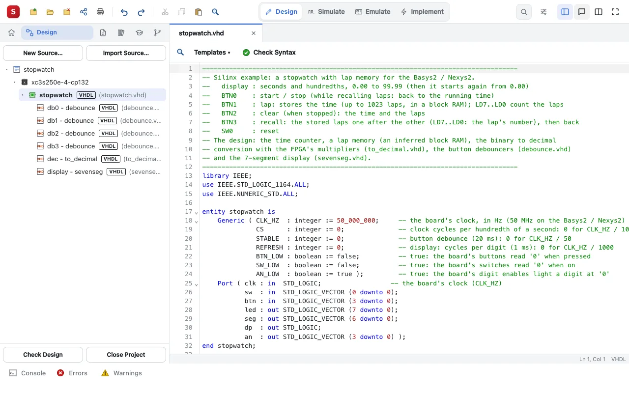
- Both languages, mixed in one project.
- Live errors and warnings, with an explanation and how to fix it for the common ones, and quick fixes.
- Auto-complete, language templates, go to definition, rename a signal everywhere it is used.
- Design checks as you type: a latch inferred, an incomplete sensitivity list, a signal never used…
Schematics
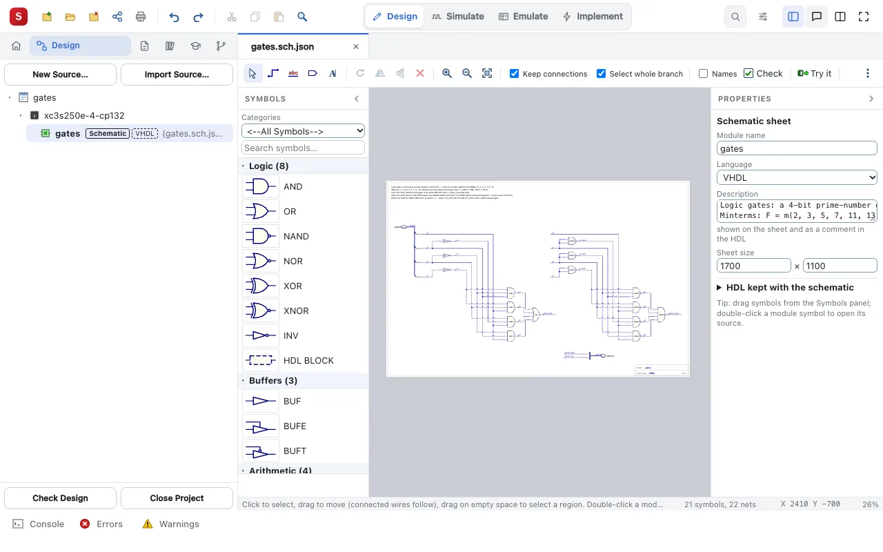
Gates, multiplexers, adders, counters, registers and your own modules as symbols, wired as in ISE's Schematic Editor. Simulate in the editor runs it live: click an input, see the wires change. Every symbol has its datasheet (Symbol Info). The adders, subtractors, comparators, counters, multiplexers, decoders, demultiplexers and encoders can be pushed into (Push into, or a double-click in a simulation): how they are built, level by level down to the gates (ADD8 of two ADD4, ADD4 of four FA1; M8_1 of two M4_1 and an M2_1), each level simulated, with the symbol's values when it is pushed into from a simulation.
State machines and ASM charts
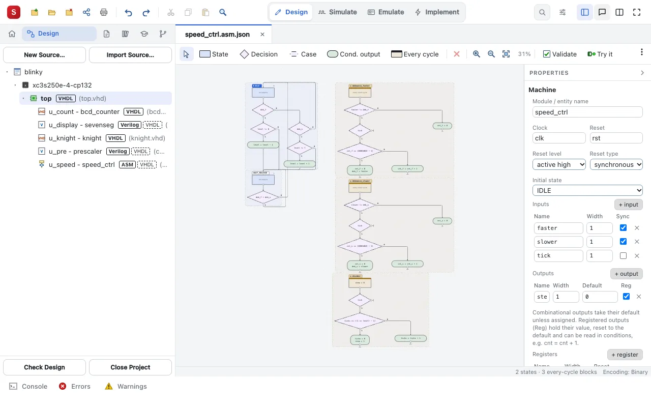
- State diagrams (FSM): states and transitions, Moore or Mealy, drawn or made by the FSM Wizard.
- ASM charts: state, decision and conditional output boxes, as the textbooks draw them.
- A state diagram becomes an ASM chart and back; Try it runs either, step by step.
Boolean algebra and Karnaugh maps
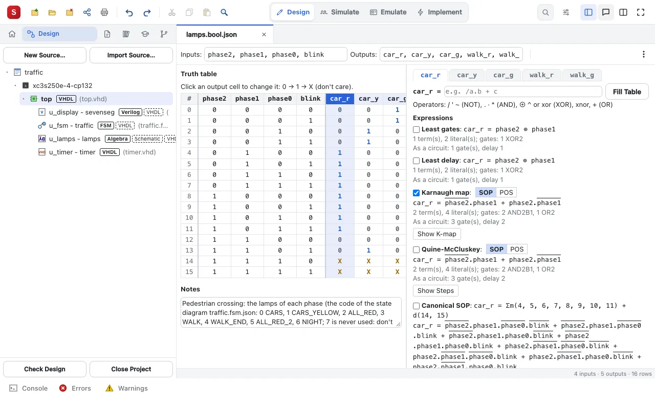
A truth table, or expressions, become a circuit: the Karnaugh map, Quine-McCluskey with its steps, the canonical forms, and the circuit each gives (its gates and delay). An expression can even be written by hand, with a pen.
Circuits, Petri nets and C
- Digital circuits on a breadboard: real 74xx and 4000 chips, see Circuits on a breadboard.
- Petri nets: places, transitions and tokens, simulated, and their hardware generated.
- C and C++: a function made into a VHDL or Verilog module, as AMD's Vitis HLS does: see Silinx HLS.
The Design pane
One row per module: its drawing first, then the HDL generated from it. A design and simulation project (no FPGA, no board) shows only the drawings, for a course that does not reach the board. In the ISE style, the Implementation view lists the constraints file and the memory images under the top module, as ISE does; in the Silinx interface, Implement and Emulate have a Files tab beside their processes' tab, with those files under the top module (on their own when the project has no top).
Next: Simulating. Every editor in detail: the features.